Have you ever heard of a 4 terminal capacitor wiring diagram? If not, you're not alone. However, this piece of knowledge can be incredibly useful to those looking to understand the ins and outs of electrical wiring and circuits. Keep reading to learn more about 4 terminal capacitor wiring diagrams and how they can help improve your electrical projects.
Many people find themselves stuck when trying to wire an electrical circuit or device involving capacitors. One common problem is figuring out which wires go where. This confusion can often lead to frustration and wasted time. Additionally, failing to understand how to properly wire a capacitor can result in costly equipment damage and even the risk of electrical shock.
A 4 terminal capacitor wiring diagram is a tool that can help you avoid these issues. This diagram shows you how to connect four wires to a capacitor so that you can easily and safely wire your device. The diagram typically includes clear instructions and labeling to ensure easy interpretation and implementation.
To summarize, a 4 terminal capacitor wiring diagram is an essential tool for anyone looking to wire capacitors safely and efficiently. By understanding how to use this tool, you can avoid costly mistakes and protect your equipment and even yourself.
The Target of 4 Terminal Capacitor Wiring Diagram
When it comes to creating electrical circuits or devices that use capacitors, ensuring proper wiring is crucial for safety and efficiency. A 4 terminal capacitor wiring diagram is a tool that can help you achieve this goal. By providing clear instructions on how to connect wires to a capacitor, this diagram makes it easy to follow proper wiring practices and avoid common mistakes.
Personally, I've found that using a 4 terminal capacitor wiring diagram has saved me time and headaches when working on electrical projects. It's a simple yet powerful tool that can make a big difference in the safety and success of your projects.
How to Use a 4 Terminal Capacitor Wiring Diagram
When using a 4 terminal capacitor wiring diagram, it's important to follow the instructions carefully and double-check your work before proceeding. Begin by identifying the four capacitor terminals and determining which wires should be connected to them. Then, using the diagram as a guide, attach each wire to the appropriate terminal, ensuring that the connections are secure and no stray wires are left exposed.
It's also important to keep safety in mind when working with electrical devices. Always make sure the device is unplugged and the power source is turned off before attempting any wiring. Additionally, use appropriate safety gear such as gloves and goggles to protect yourself from electrical shock and other hazards.
Common Mistakes to Avoid When Using a 4 Terminal Capacitor Wiring Diagram
One common mistake when using a 4 terminal capacitor wiring diagram is failing to identify the correct wires. Make sure you have a clear understanding of which wires should be connected to which terminals before attempting to wire your capacitor.
Another mistake to avoid is failing to properly secure your wire connections. Loose or exposed wires can lead to electrical shock and equipment damage, so be sure to double-check your connections and ensure that they are secure.
Benefits of Using a 4 Terminal Capacitor Wiring Diagram
Using a 4 terminal capacitor wiring diagram has numerous benefits. First and foremost, this tool helps ensure that your wiring is correct, reducing the risk of equipment damage and electrical shock. Additionally, it can save you time and frustration by providing clear and concise instructions for wiring your capacitor. Finally, using a 4 terminal capacitor wiring diagram can help increase your confidence when working with electrical circuits and devices.
Question and Answer
- Q: What is a capacitor?
- A: A capacitor is an electronic component that stores electrical charge.
- Q: Why is wiring a capacitor correctly important?
- A: Wiring a capacitor correctly is important for safety reasons and to ensure the proper functioning of electrical circuits and devices.
- Q: What are the four terminals on a capacitor?
- A: The four terminals on a capacitor are typically labeled C, HERM, FAN, and COM.
- Q: Can using a 4 terminal capacitor wiring diagram help save time and frustration?
- A: Yes, using a 4 terminal capacitor wiring diagram can help simplify the wiring process and reduce the risk of mistakes, saving you both time and frustration.
Conclusion
A 4 terminal capacitor wiring diagram is an essential tool for anyone working with electrical circuits or devices involving capacitors. By helping you avoid common mistakes and ensuring proper wiring, this diagram can save you time, frustration, and even equipment damage or electrical shock. Whether you're a novice or an experienced electrician, using a 4 terminal capacitor wiring diagram can help you achieve your electrical goals safely and efficiently.
Gallery
250v 100uf Cd60 Motor Starting Capacitor With 4 Pins Terminal Lowes
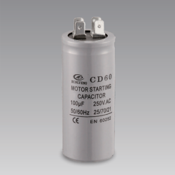
Photo Credit by: bing.com / capacitor cd60 electrolytic 100uf 250v
Understanding The 4 Terminal Capacitor Wiring Diagram | WIREGRAM

Photo Credit by: bing.com /
Capacitors - Series And Parallel - HVAC School

Photo Credit by: bing.com / capacitors parallel capacitor capacitance hvacrschool tech
Exhaust Fan Capacitor Wiring - Electronic Diagram

Photo Credit by: bing.com / capacitor
250v 100uf Cd60 Motor Starting Capacitor With 4 Pins Terminal Lowes
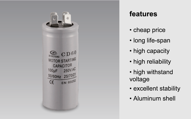
Photo Credit by: bing.com / capacitor cd60 100uf electrolytic lowes 250v